
Verifying Every Assembly Before It Reaches Your Customer
Inspection tells us whether a PCB has been assembled correctly. Testing tells us whether it performs as intended.
Our testing processes combine automated inspection, electrical testing, programming and functional verification to ensure product quality.
Discuss Your Testing Requirements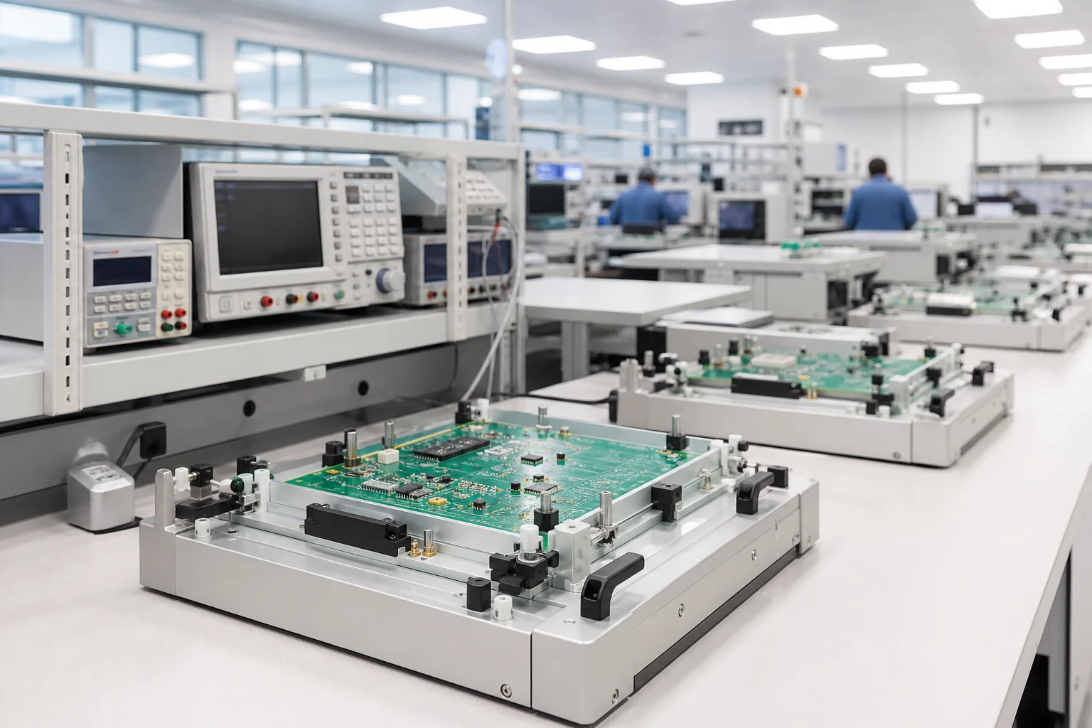
Inspection Before Testing
AOI — Automated Optical Inspection
Detecting visible assembly defects including:
- Missing components
- Wrong components
- Component offset
- Solder bridges
- Soldering defects
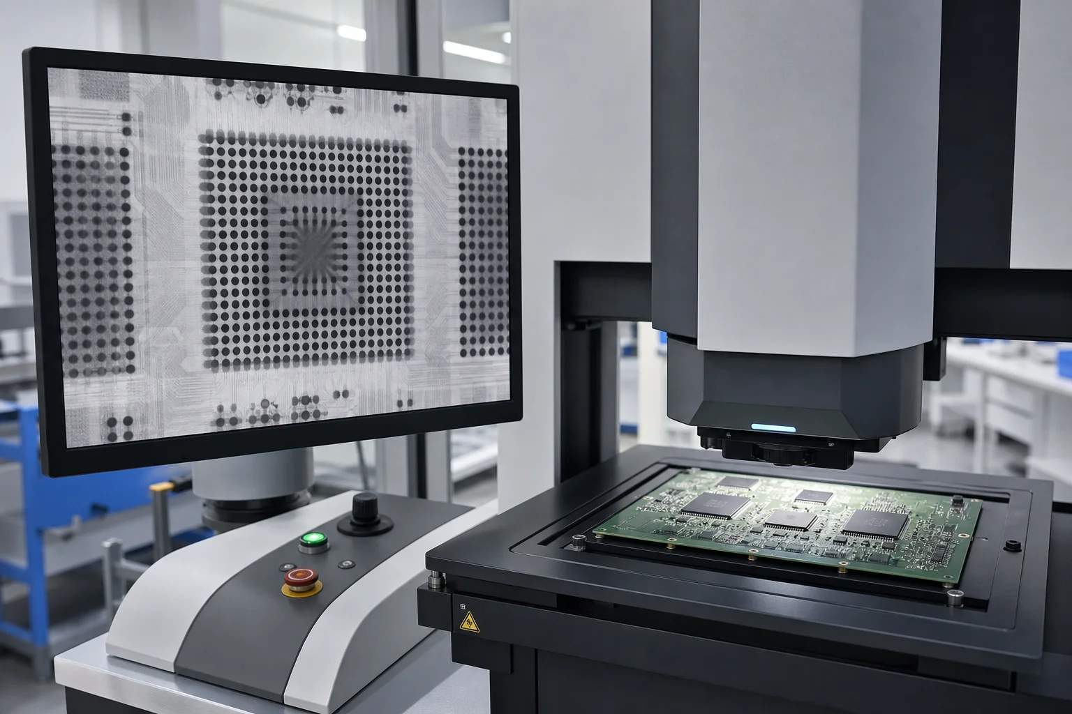
X-Ray Inspection
For hidden solder joints and advanced packages such as BGA and QFN.
Inspection can identify:
- Voids
- Opens
- Shorts
- Solder joint defects
Electrical Verification
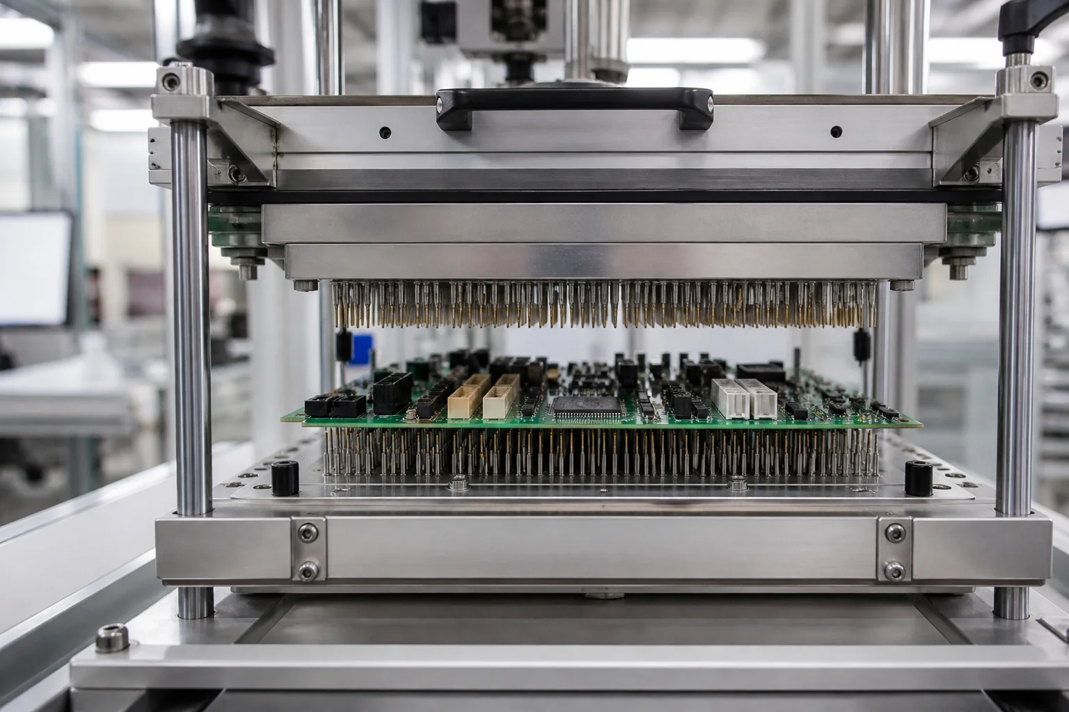
ICT — In-Circuit Test
ICT checks electrical and component-level conditions including:
Programming & Configuration
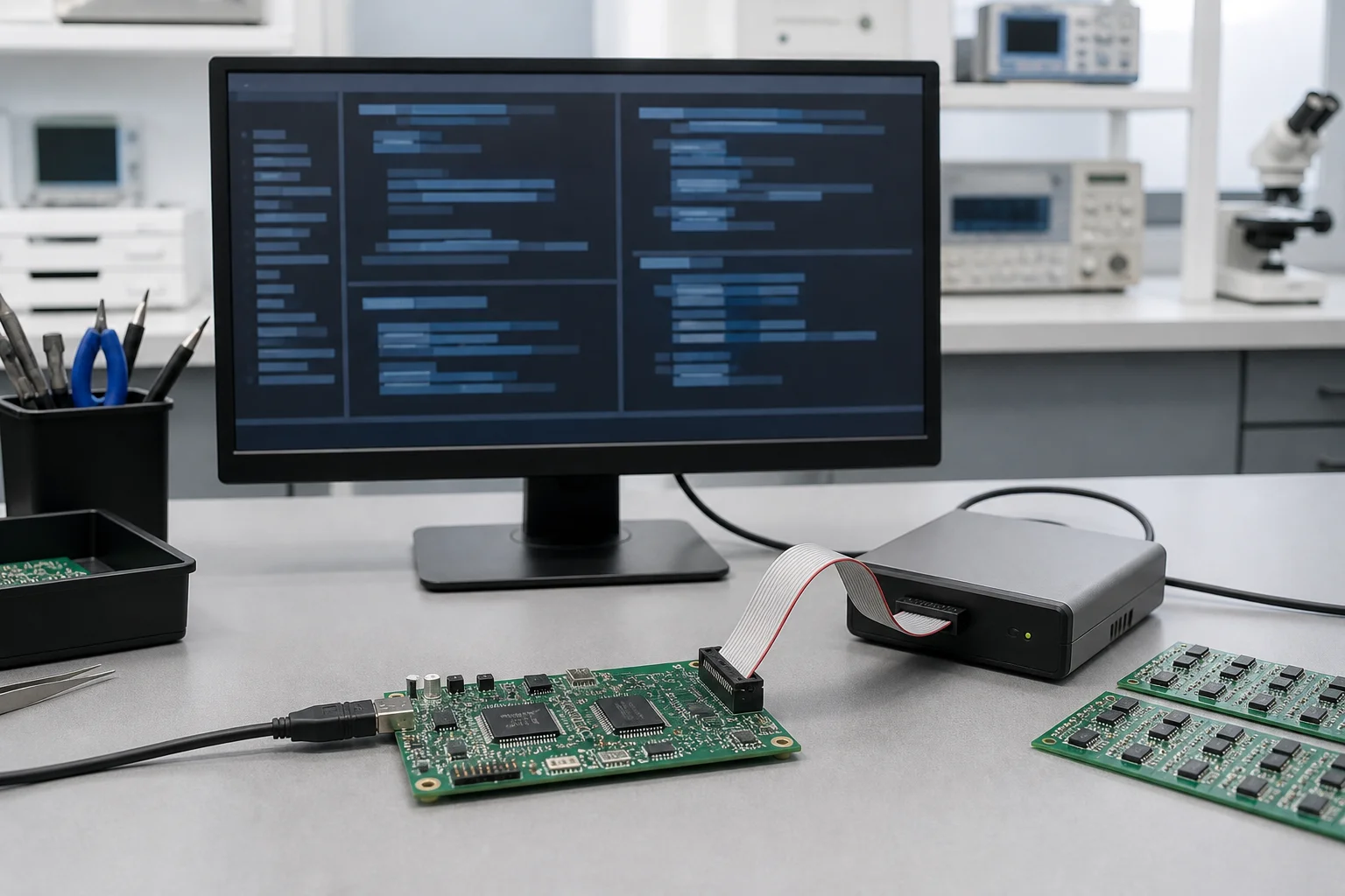
Where required, we can integrate programming and configuration into the manufacturing process.
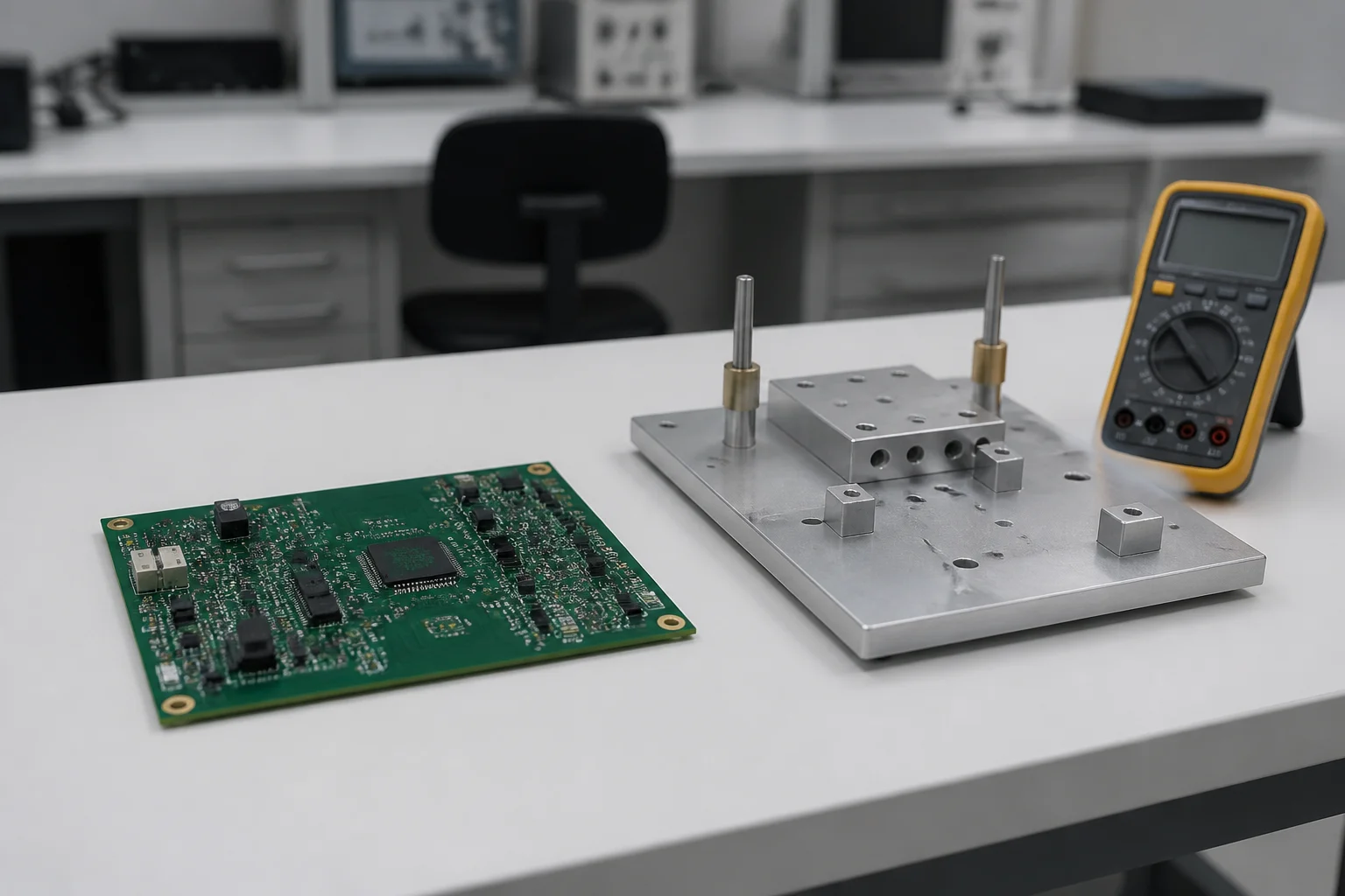
Functional Testing
Functional testing evaluates whether the assembled product actually performs according to its intended application.
Depending on the product, testing may include:
Reliability Testing
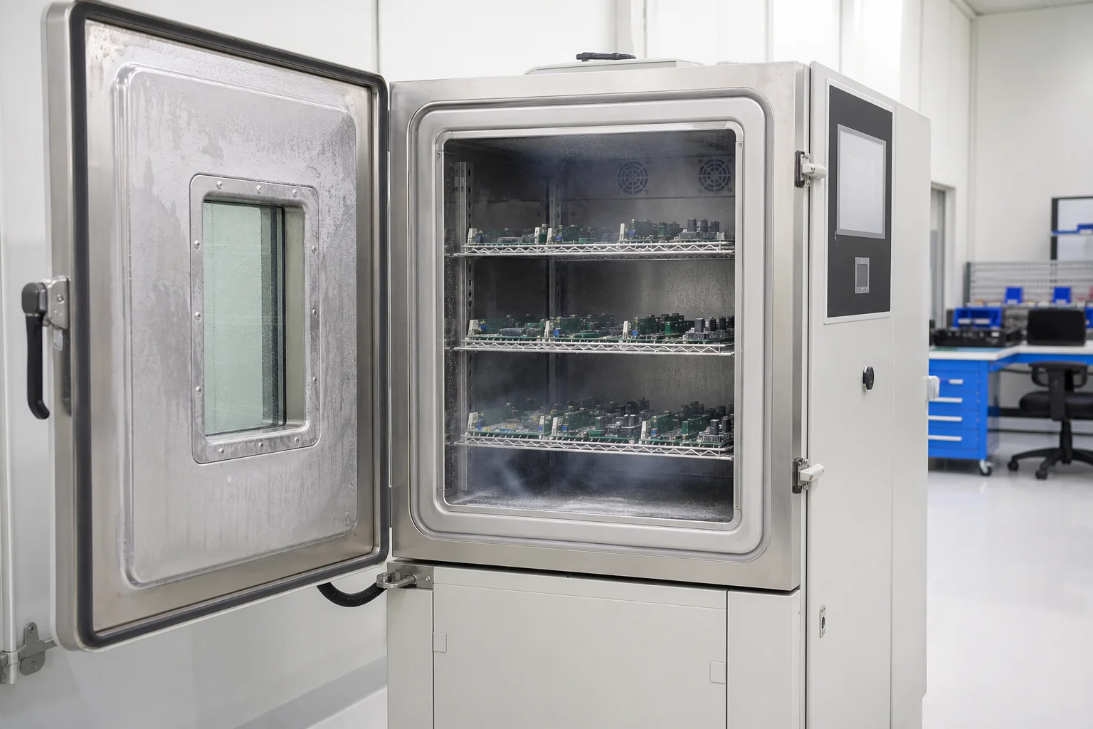
According to project requirements, additional testing can be incorporated into the manufacturing process.
Quality Data You Can Trust
Test results can be integrated into the manufacturing quality process to provide greater visibility into:

Frequently Asked Questions
How do you test a PCBA?
Depending on the product: AOI after reflow, X-ray (AXI) for hidden joints, ICT or flying probe for electrical checks, and functional testing (FCT) to verify the product works as specified. The methods are complementary — the test plan is defined per product.
What does AOI check, and can it find all problems?
AOI uses cameras and algorithms to check visible features — component position, missing parts, offset, polarity, and solder joints. It has limits on joints hidden under BGA or bottom-terminated devices, which is why some products need X-ray as a supplement.
What is the difference between ICT and FCT?
ICT leans toward structure, electrical connectivity, and component parameters at test points. FCT focuses on whether the product actually works as required — I/O, power, communication, buttons, sensors. The two are complementary.
How do you handle a defective assembly?
Rework restores a nonconforming solder joint, component, or assembly to specification under a controlled process; repair handles more complex issues such as damaged conductors, pads, or laminate structure. Both avoid shipping a nonconforming unit.
Is 100% inspection available?
Yes — every assembly passes AOI after reflow as standard; X-ray coverage, ICT, and FCT are defined per product in the test plan based on package mix and functional risk.
Quality Is More Than Visual Inspection
Our testing capabilities help verify that your PCBA is not only assembled correctly but also performs as required.
Discuss Your Testing Requirements