HVAC Control Solutions
HVAC control solutions built around the whole climate system
Custom control electronics that coordinate sensing, decision logic, power interfaces and HVAC loads—from the first operating sequence through a production-ready PCBA.
- Temperature & humidity sensing
- Compressor & fan control
- Fault response
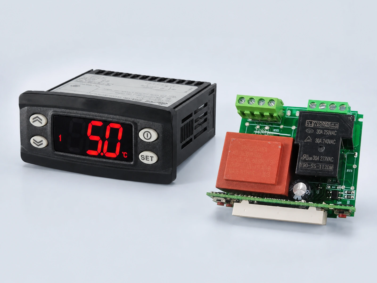
HVAC Control Challenges
Stable comfort depends on coordinated control
An HVAC controller has to interpret changing conditions, sequence multiple loads and protect the equipment when a sensor, actuator or operating state moves outside its expected range.
Changing thermal loads
Balance setpoint response, cycling behavior and energy use as room and system conditions change.
Multiple controlled devices
Coordinate compressors, fans, pumps, valves, dampers and auxiliary loads in the correct sequence.
Protection and recovery
Define safe reactions to sensor faults, abnormal temperatures, water level conditions and load feedback.
Interface consistency
Keep buttons, displays, remote inputs and system states understandable across normal and fault modes.
Smart HVAC Control Architecture
A closed control loop from conditions to equipment response
The reference path below frames the control-board design and engineering discussion. The final inputs, outputs, isolation, protection and control method are selected for the actual equipment.
- Temperature & humidity
- Pressure or flow
- Water level & switches
- Motor or load feedback
- Operating sequence
- Setpoint logic
- Timing & interlocks
- Diagnostics & fault states
- Compressor stages
- AC / DC / BLDC fans
- Pumps, valves & dampers
- Heating or auxiliary outputs
Engineering note: Mains switching, motor interfaces, isolation, creepage and clearance, electromagnetic compatibility and equipment-level compliance must be reviewed against the complete product and its target market.
Core Control Functions
Define the functions around the equipment
The controller should express the HVAC operating sequence clearly while keeping sensing, power handling, user interaction and fault behavior testable.
Temperature & Humidity
Acquire sensor inputs, manage setpoints and control response bands for the real environment.
Stage & Cycle Control
Apply start delays, minimum run times, anti-short-cycle logic and requested operating stages.
Fan & Motor Control
Support relays, speed commands, PWM or feedback interfaces appropriate to the motor system.
Pumps, Valves & Dampers
Sequence auxiliary loads and confirm the expected system state where feedback is available.
Display & User Modes
Coordinate keys, touch panels, indicators, timers and service parameters with controller states.
Fault Detection & Recovery
Handle abnormal sensor values, load conditions and recovery behavior according to the specification.
Optional Connectivity
Connect the controller when the system needs it
Connectivity can support setup, remote control, status reporting and maintenance. It remains a defined subsystem of the HVAC solution rather than the purpose of the page.
Explore smart-home and connected-device capabilities →Network access for remote settings, status and cloud-connected functions.
Local commissioning, setup and nearby device interaction.
Wired communication with equipment, panels or supervisory systems.
Planned update paths with product-specific validation and recovery behavior.
Application Experience
Control patterns for different HVAC products
These examples show application contexts. Specific board platforms, configurations and product features belong on the corresponding product page.
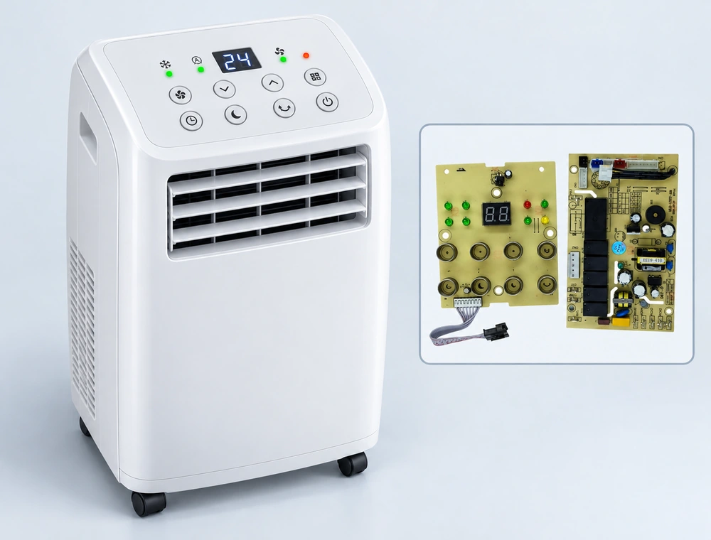
Portable Air Conditioning
Coordinate compressor, fan, water management, defrost, timers, display and fault indication.
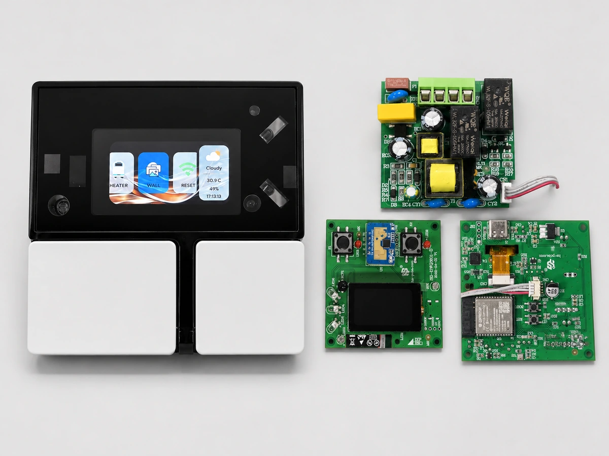
Central HVAC Controllers
Manage temperature setpoints, heating and cooling modes, fan speeds, schedules and system interfaces.
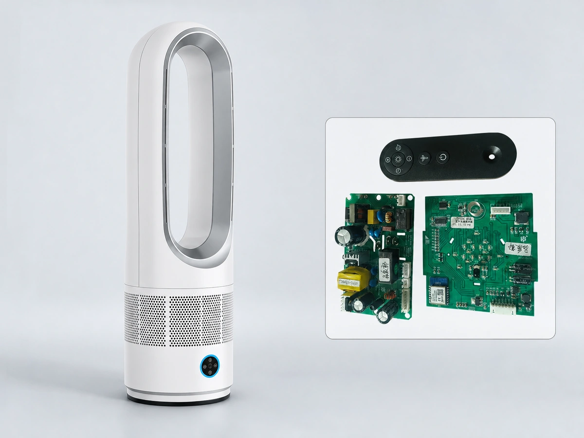
Fans & Ventilation
Combine multi-speed airflow, swing or damper control, environmental sensing and user modes.
Looking for specific portable AC, air-cooler or fan controller boards? Continue to the product catalogue rather than comparing product models on this solution page.
View Cooling Products →Engineering to Production
Move from operating requirements to repeatable production
The solution page defines the application. The linked capability pages explain how the electronics are designed, verified and scaled.
Engineering Review
Loads, sensors, interfaces, constraints and operating sequence.
Prototype
Hardware, firmware and functional behavior evaluated together.
NPI
Design, assembly, test and pilot-process risks closed before release.
Mass Production
Released processes, traceability and repeatable functional verification.
Frequently Asked Questions
Planning an HVAC control project
The answers establish project scope without replacing an engineering review of the equipment, loads and target-market requirements.
What is an HVAC control solution?
An HVAC control solution coordinates temperature and environmental sensing, embedded control logic, power interfaces and controlled loads such as compressors, fans, pumps, dampers or valves. Its exact architecture depends on the equipment and operating requirements.
Can HS customize an HVAC control PCBA for our equipment?
Yes. The design can be developed around your supply, loads, sensors, operating sequence, display, communications, enclosure and target market. Feasibility and the final scope are confirmed during engineering review.
How are compressor and fan controls defined?
The control strategy is defined from the actual compressor, fan motor and power interface specifications. It may include staged outputs, speed commands, timing constraints, feedback signals, interlocks and fault responses.
Can WiFi, Bluetooth BLE or RS485 be included?
Yes. Connectivity can be included when the product needs commissioning, remote settings, monitoring, service access or integration with another system. The interface and security requirements should be defined before hardware and firmware are finalized.
How do you test an HVAC controller PCBA?
A project-specific plan can combine inspection, programming, electrical checks and functional testing. The functional fixture should exercise the relevant sensor inputs, outputs, communications, display and fault states defined for the controller.
What information is needed to start an HVAC controller project?
Provide the equipment type, supply and load ratings, compressor and fan details, sensors, operating sequence, user interface, communications, enclosure constraints, target markets, expected volume and available design files.
Start With the System Requirements
Bring us your HVAC control challenge
Share the equipment type, loads, sensors, interface, communication needs, target market and expected volume. We will use them to frame the engineering review.