APPLICATIONS & SOLUTIONS / MOTOR CONTROL
Motor Control Solutions for Predictable Motion
Coordinate the motor, drive stage, feedback, embedded control and protection strategy as one system—so speed, torque, direction and stopping behavior match the real mechanical load.
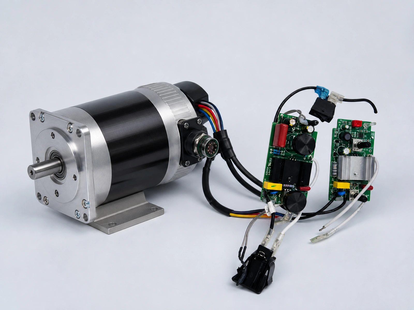
MOTOR CONTROL CHALLENGES
The load defines the controller
Motor voltage alone does not define the electronics. Starting load, operating profile, feedback, braking, heat and mechanical limits determine how the drive must behave.
Starting & peak load
Size the power stage around startup, stall and transient current rather than nominal current alone.
Stable speed
Match PWM, commutation and feedback strategy to the required speed range and load variation.
Heat & efficiency
Review switching loss, copper loss, airflow, enclosure conditions and duty cycle together.
Fault response
Define what the product should do during stall, overload, sensor loss, overtemperature or undervoltage.
SMART MOTOR CONTROL ARCHITECTURE
A closed control path from command to motion
The controller converts a product command into a controlled electrical output, measures the real response and adjusts behavior while monitoring operating limits.
Product Input
Buttons, HMI, analog command, communication interface or programmed operating mode.
MCU Control
Speed profile, direction, ramping, commutation, state logic and fault handling.
Drive Stage
MOSFETs, gate driving, current paths and power delivery matched to the motor and load.
Motor & Mechanics
BLDC, brushed DC motor, actuator, pump or fan operating within the real assembly.
Feedback & Protection
Hall sensors, encoder, current, voltage and temperature information returned to control.
MOTOR & DRIVE CHOICES
Select the control method around the motion requirement
Different motor types and motion profiles require different drive electronics, feedback and firmware. The final selection follows the product specification and mechanical load.
BLDC Control
Electronic commutation for efficient, controllable motion where service life, noise or speed range matter.
- Hall-based or sensorless options
- Startup and commutation logic
- Current and thermal monitoring
Brushed DC Control
Direction and PWM speed control for compact mechanisms, pumps, fans and cost-sensitive actuators.
- H-bridge or single-direction drive
- Soft start and braking behavior
- Overcurrent and stall response
Actuator Control
Controlled linear or rotary movement using limit inputs, position feedback and coordinated stop logic.
- Limit switch integration
- Encoder or position sensing
- Travel and obstruction logic
CORE CONTROL FUNCTIONS
Control behavior built around the product
The board coordinates motion with the rest of the product instead of treating the motor as an isolated load.
Speed & Direction
PWM, commutation and direction logic aligned with the usable motion range.
Acceleration & Braking
Ramps and stopping behavior designed around inertia, comfort and mechanical stress.
Feedback Processing
Hall, encoder, current and position inputs translated into control decisions.
Load Detection
Current or feedback patterns used to identify abnormal load, obstruction or stall.
Protection Logic
Response to overcurrent, overtemperature, undervoltage and missing feedback.
System Interfaces
Motor behavior coordinated with sensors, displays, host controllers and communication.
APPLICATION EXPERIENCE
Motion control across products and equipment
These examples show solution contexts. Specific product platforms and manufacturing processes remain on their respective product and capability pages.
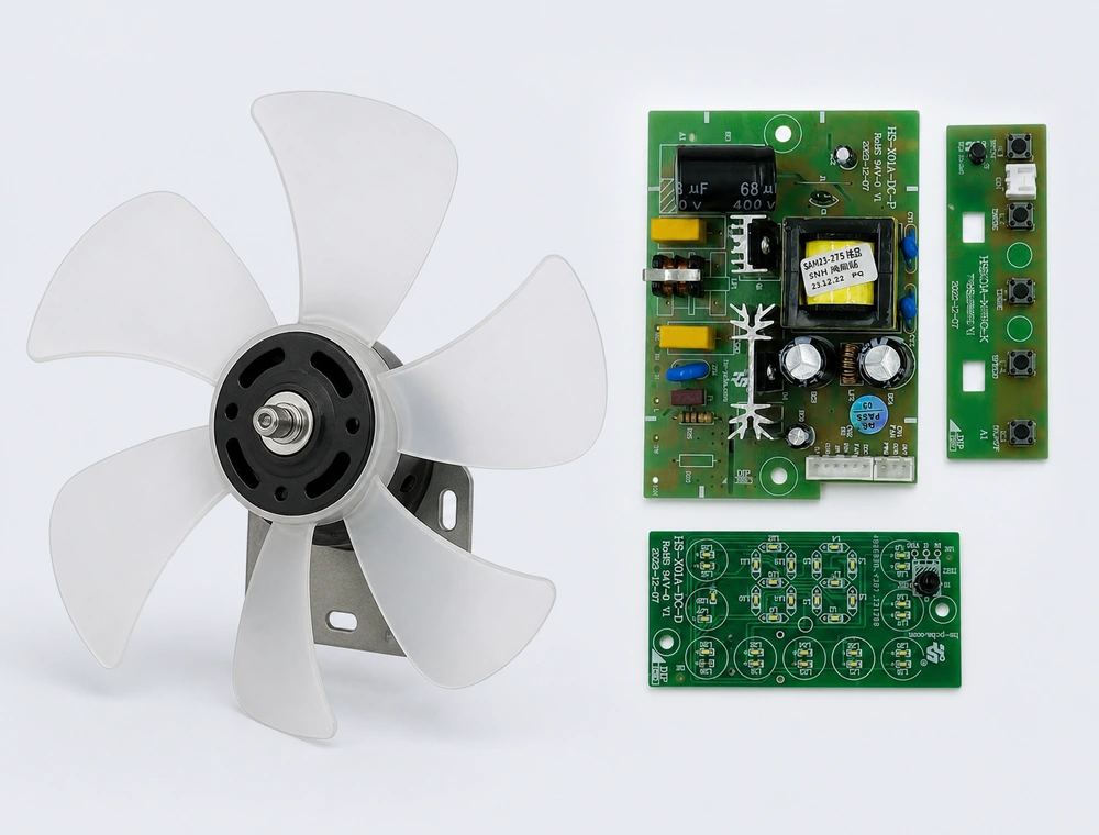
Fans & Blowers
Speed regulation, startup behavior, airflow response and stall protection for variable-load systems.
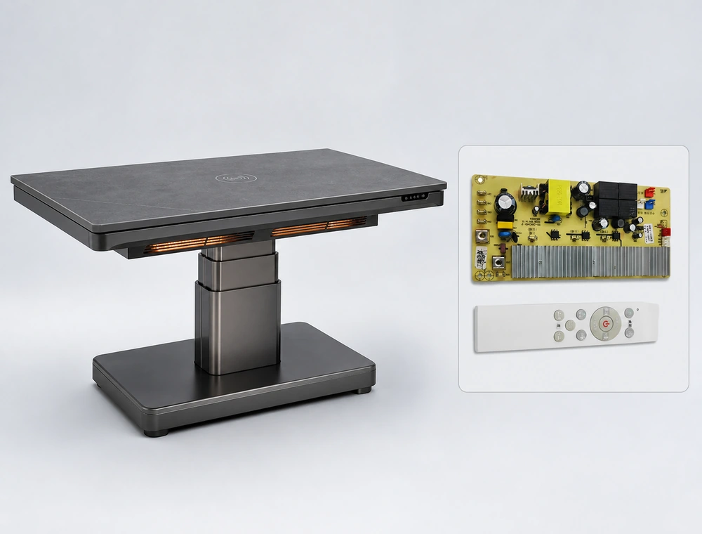
Actuators & Lifting
Direction, soft start, travel limits, position feedback and obstruction response.
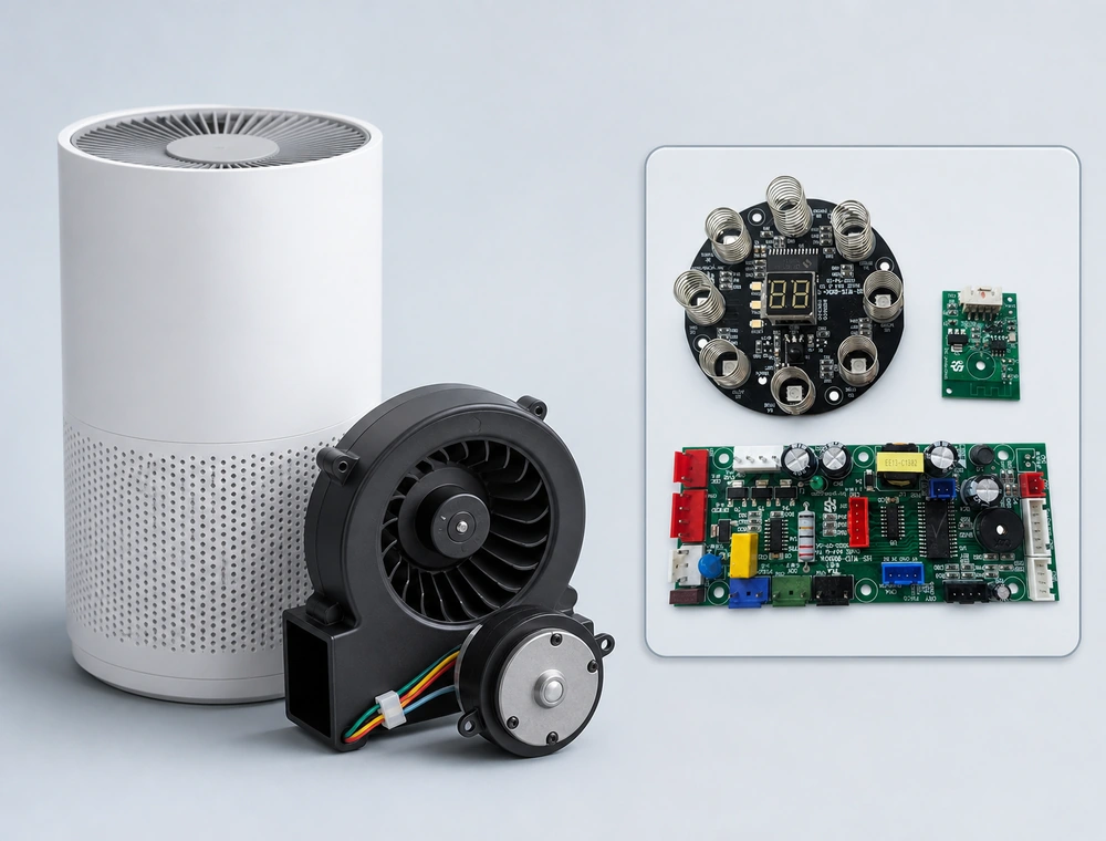
Air Purifier Fan Motors
Quiet multi-speed airflow control with soft start, speed feedback and abnormal-load protection.
CONTROL & LOAD VERIFICATION
Test motion under the conditions that matter
Functional verification should cover the electrical controller and the real motor-load behavior. Test limits and fixtures are defined according to the product requirement.
Startup & Stall
Observe inrush, startup time, recovery and the defined response to a blocked or overloaded mechanism.
Speed & Feedback
Verify the commanded range, regulation under load and expected Hall or encoder signals.
Thermal Behavior
Check power-stage and component temperatures across duty cycle, load and enclosure conditions.
Fault Handling
Confirm shutdown, retry, indication and recovery behavior for the faults defined by the product.
ENGINEERING TO PRODUCTION
Develop the control and the production path together
Architecture, prototype loading, functional testing and production controls are connected so the approved motion behavior can be repeated from pilot units through volume manufacturing.
Engineering Review
Define motor data, mechanical load, motion profile, feedback, interfaces and fault behavior.
Prototype & Load Test
Bring up the drive and firmware, then validate key motion states on the representative mechanism.
NPI & Pilot
Close design, assembly, programming and functional-test risks before production release.
Mass Production
Build the approved controller with controlled processes, test coverage and revision traceability.
FAQ
Motor Control Solution FAQs
These questions help define the electrical, mechanical and firmware boundary before controller development begins.
What information is needed to develop a motor control solution?
Useful inputs include the motor type and datasheet, supply voltage, continuous and peak current, mechanical load, speed or position range, duty cycle, feedback devices, enclosure conditions, interfaces, fault behavior and target production volume.
Do you support BLDC and brushed DC motor control?
Motor control electronics can be developed for BLDC and brushed DC applications when the motor, load and performance requirements are defined. The drive topology, sensing and firmware approach are selected for the specific application.
Can the controller use Hall sensors or an encoder?
Yes. Hall sensors, incremental encoders, position sensors and limit inputs can be integrated when they match the required commutation, speed, position or travel-control strategy.
How are motor stall and overload conditions handled?
The response can use current, missing motion feedback, timing and temperature information. The controller may limit output, stop, retry or report a fault according to the product's approved safety and operating logic.
Can one control board manage the motor and other product functions?
Yes, when processor resources, power architecture and interfaces support the complete requirement. Motor control can be coordinated with sensors, heating, lighting, displays, buttons and communication within one product controller.
How do you verify a motor controller before mass production?
Verification is defined for the application and may include startup, speed, direction, load, stall, feedback, current, thermal and fault-recovery checks. NPI then confirms programming, fixtures, test coverage and the repeatability of the production process.
Bring the motor, load and control requirements into one engineering discussion
Share the motor data, mechanism, motion profile and expected fault behavior. HS-PCBA can review the drive electronics, feedback, firmware and production path as one system.